Lightning-fast testing with electrical imaging reduces costs
Time is a scarce resource. "Electrical imaging" (German ‚Elektrische Fotografie‘) helps to safe time in the form of the EFx system (patented) - and is thus an alternative to the widespread in-circuit test procedure.
The in-circuit test method (ICT), which is still widely used today, is the most popular test method for electronic assemblies worldwide. Within this method each component is electrically stimulated sequentially and the reaction to it is evaluated according to the required setting time. A classic in-circuit tester with many measurement channels depends on the board’s complexity and can therefore take minutes for a test. With the new type of electronic photography on which ATEip GmbH's patented Efx solution is based, only a few milliseconds are needed for a single, comprehensive data acquisition and evaluation of a complete board for boards of comparable complexity. The methodology used in the Efx system to mathematically calculate measurement data in this snapshot process has been known in theory for years. Until now, however, the low computer power available at low cost and the equally limited integration density of the components have prevented the practical implementation of this method in assembly test systems. In the future, however, the further development of existing measurement techniques combined with methods of AI in board testing will gradually lead to a fundamental paradigm shift.
How the system works
In electronic imaging, all contactable electrical networks of the assembly are stimulated simultaneously with a series of rapidly changing signals. The resulting voltage ratios in the circuit and the current flowing into the network are recorded and form an electronic snapshot of the entire assembly.
"The test depth achieved with this method is considerably greater than with the "classic" in-circuit test, and at significantly less expense."
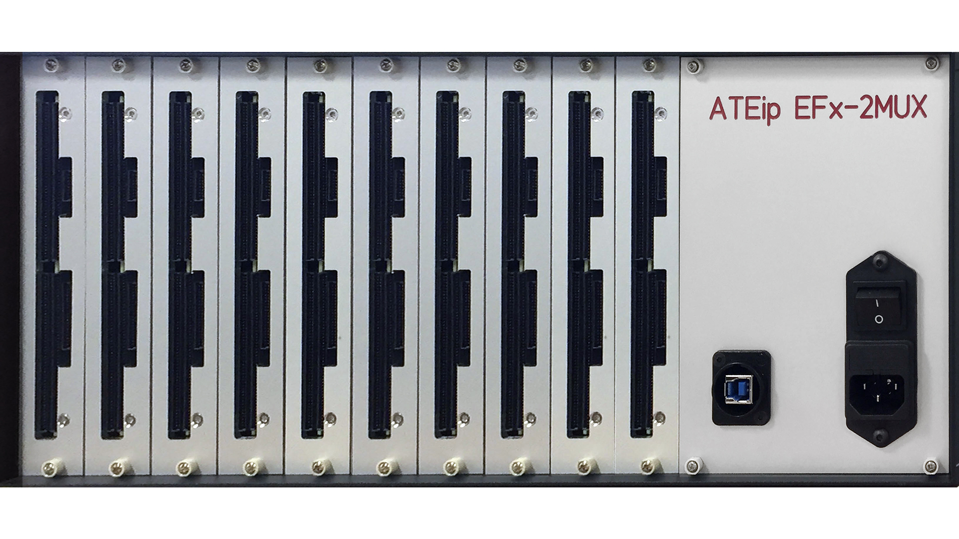
Figure 1: The tester comprises a complete set of instruments per test channel (Fig.: ATEip Automatic Test Equipment ip GmbH)
With this test technology, many layers of analog measured values of an assembly are mapped, digitized and the data stored for analysis in one test run. Each of the synchronously recorded circuit layers can be immediately evaluated as required for individual measuring points as well as for all measuring points in total. In the following analysis of all synchronously mapped layers, the calculated electrical networks are then produced and compared with the specifications for the respective test object. All electrical parameters between all measuring points are determined simultaneously. The measured value yield per pin and per recorded parameter increases with each recording or test by the square of the used measured value points (resolution) of the electrical photography. With three simultaneously recorded parameters, the EFx tester (Fig. 1) with a resolution of 64 measurement points corresponds to a classic ICT system with a maximum of 12,288 test channels (64 x 64 x 3). Depending on the configuration of the Efx tester and depending on the design of the test adapter, it is also possible to measure assemblies manufactured in various panels in parallel - a further advantage that increases the throughput of the tester and thus its cost-effectiveness. Functional tests are also possible via boundary-scan according to IEEE standard 1149.1 (JTAG).
Broad test spectrum
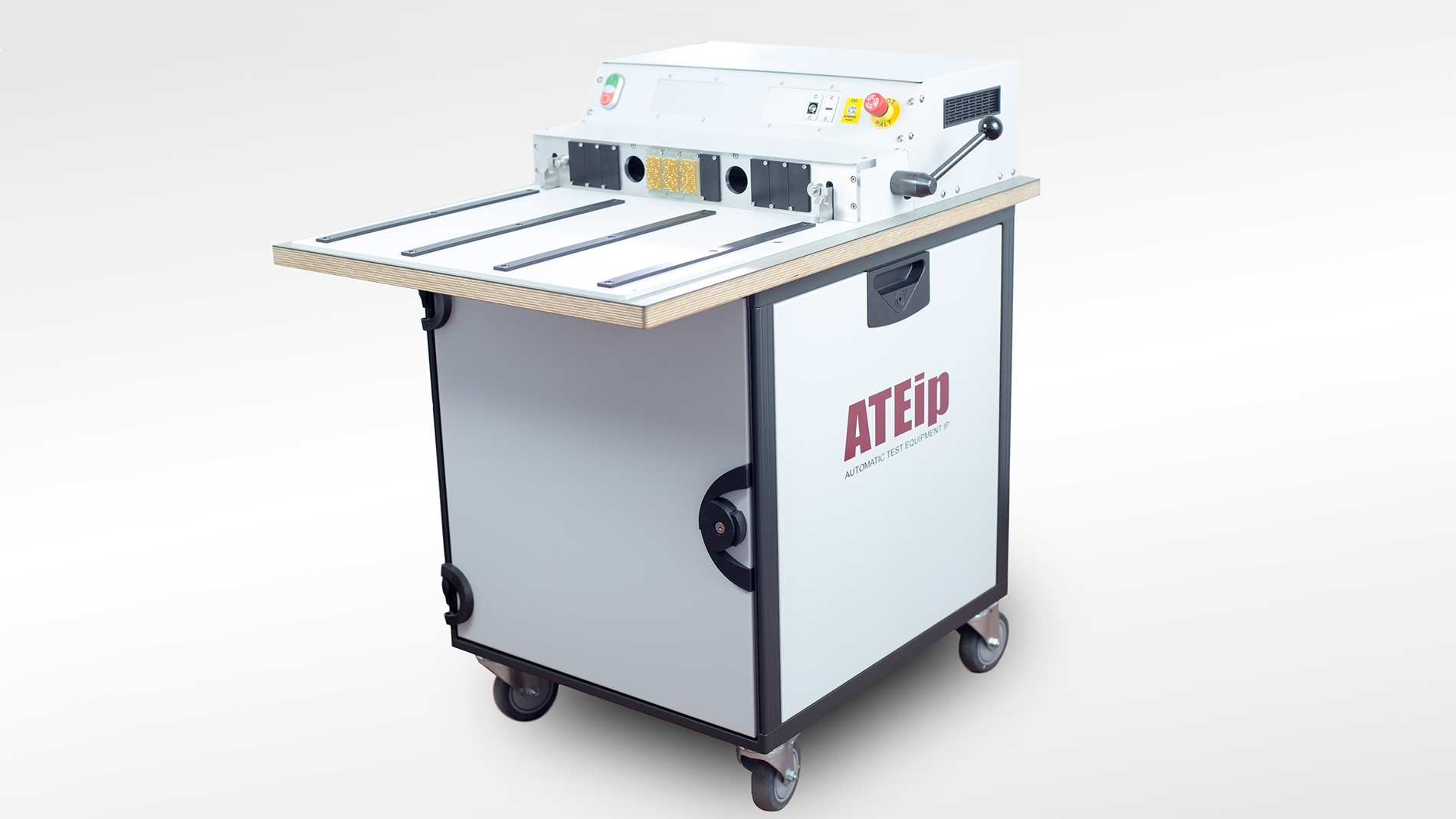
Fig. 2: EFx-test system, based on two 19“ racks for Efx-, In-Circuit- and Functional-test (Fig.: ATEip Automatic Test Equipment ip GmbH)
The novel, potential-free test system architecture basically manages without the relay matrix - which is otherwise common and also susceptible due to its cross-matrix architecture. This ensures high system reliability. However, a reliably operating relay channel switching unit is also available as an option. With this, however, only the four contacts of a test channel are switched on and off, no heavy-duty cross-matrix switching.
The tests with the different bursts run in parallel on all channels. For each pair of test channels, images of the impedances of both individual components and entire circuit clusters are obtained and calculated in the units resistance, capacitance and inductance. A scope is available at each test point for measurements under operating conditions (functional test). In standard power-up procedures, each test point of the assembly is recorded under operating conditions. Separate tests of the contacts on the part of the adaptation (contact and short-circuit diagnosis) are generally not necessary because such possible faults are immediately detected and displayed by the EFx system.
Conclusion
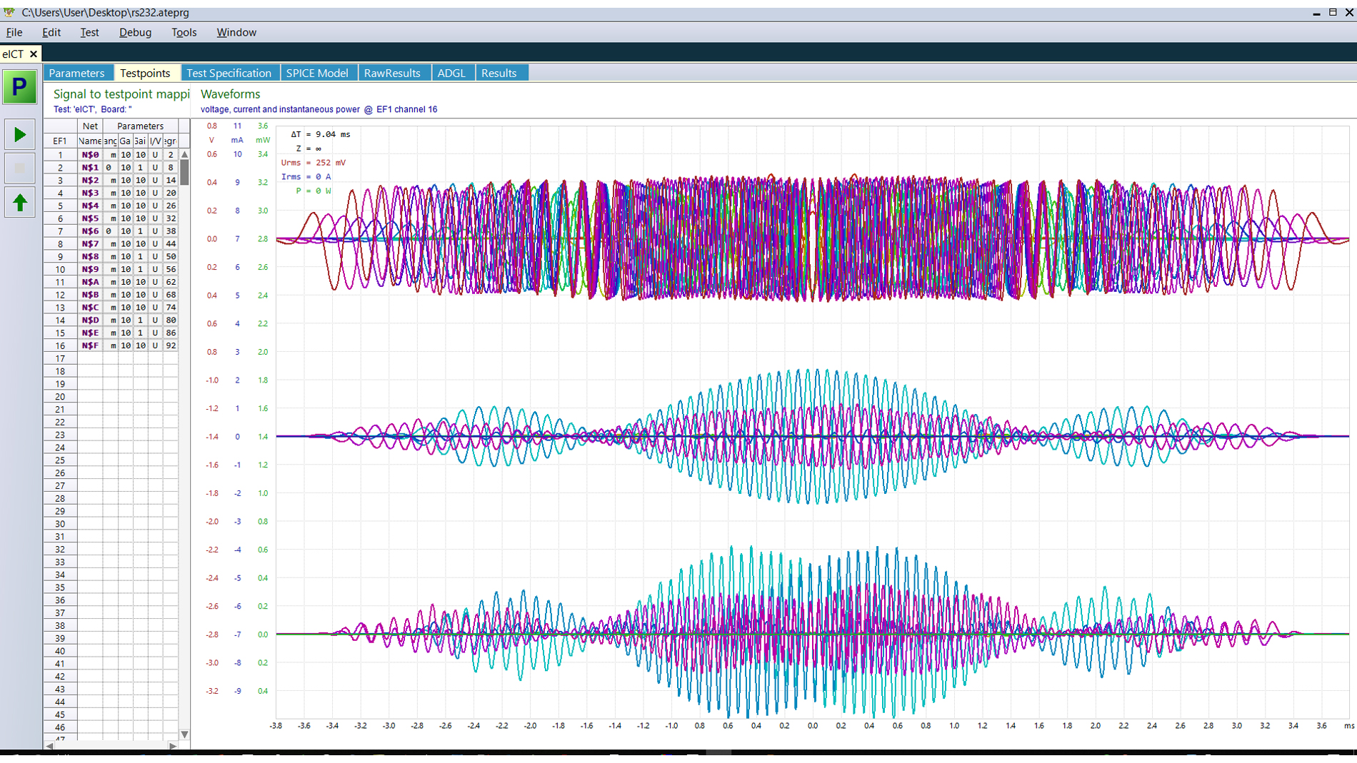
Fig. 3: Complex EFx test signal for 16 circuit nodes for total test time of 9,4 ms (Fig.: ATEip Automatic Test Equipment ip GmbH)
The system (Fig. 2, 3) thus requires very few test points for differentiated statements about the test object. As the proof-of-concept carried out by independent bodies showed, stable and at any time reliably reproducible measurement results of the assemblies are thus achieved. Due to the fact that only a few test points are required, the effort in the run-up to the tests is significantly reduced. This makes the long times for testing, programming and debugging a thing of the past. The test programs are obtained - as is usually the case - from the existing CAD development data of the board, as are the manufacturing data for the adapters.
This test system allows the economical and efficient testing of complex assemblies - manufactured separately as well as in a panel. In addition, all relevant possibilities for integration in production environments can be realized. The investment volume for an EFx test system is comparable to that of an in-circuit tester. However, the new technology offers significant advantages both in terms of costs and time required for programming as well as in ongoing system operation (cost of ownership)
Contact
Frank Grossmann,
ATEip GmbH | CCO | Sales & Support Manager
Dipl.Ing. Communication Technology, f.grossmann@ateip.de