A lot has happened since the first flying probe testers had been introduced to the market more than twenty years ago. Not only have the fields of application expanded, but also the requirements on the hardware and software performance of the systems.
Today, various system aspects are coming to the fore that did not seem so decisive at the time. One example is the drive concept of the test axes. In the development of the flying probe testers, SPEA used linear motors and optical encoders for all drive axes right from the start. Other systems with planar motors and spindle drives never reach the accuracy and speed of linear motors due to their concept.
"The drive concept determines the speed and precision required today for the flying probe test.“
This is because flying probe systems have long been used in high-volume series production - and here the cycle time determines the cycle.
In addition to pure in-circuit testing, the systems must also cover more and more test requirements, such as testing LEDs, detecting component deflections and also performing functional tests. Furthermore, component miniaturization and increasing packing densities require the contacting of smallest geometries, i.e. pad sizes down to 50 µm.
A fast availability "time to market" is a general trump card for flying probe systems. This is achieved by eliminating the need for adapters and creating test programs quickly and easily. Flexibility and sustainability - both of the test systems and the manufacturers - are an absolute must. Another decisive factor is that flying probe testers can be flexibly configured according to customer requirements and are suitable for testing the top and bottom sides. Further aspects are the operation both in the line and stand-alone as well as the problem-free integration into automation concepts and higher-level MES systems.
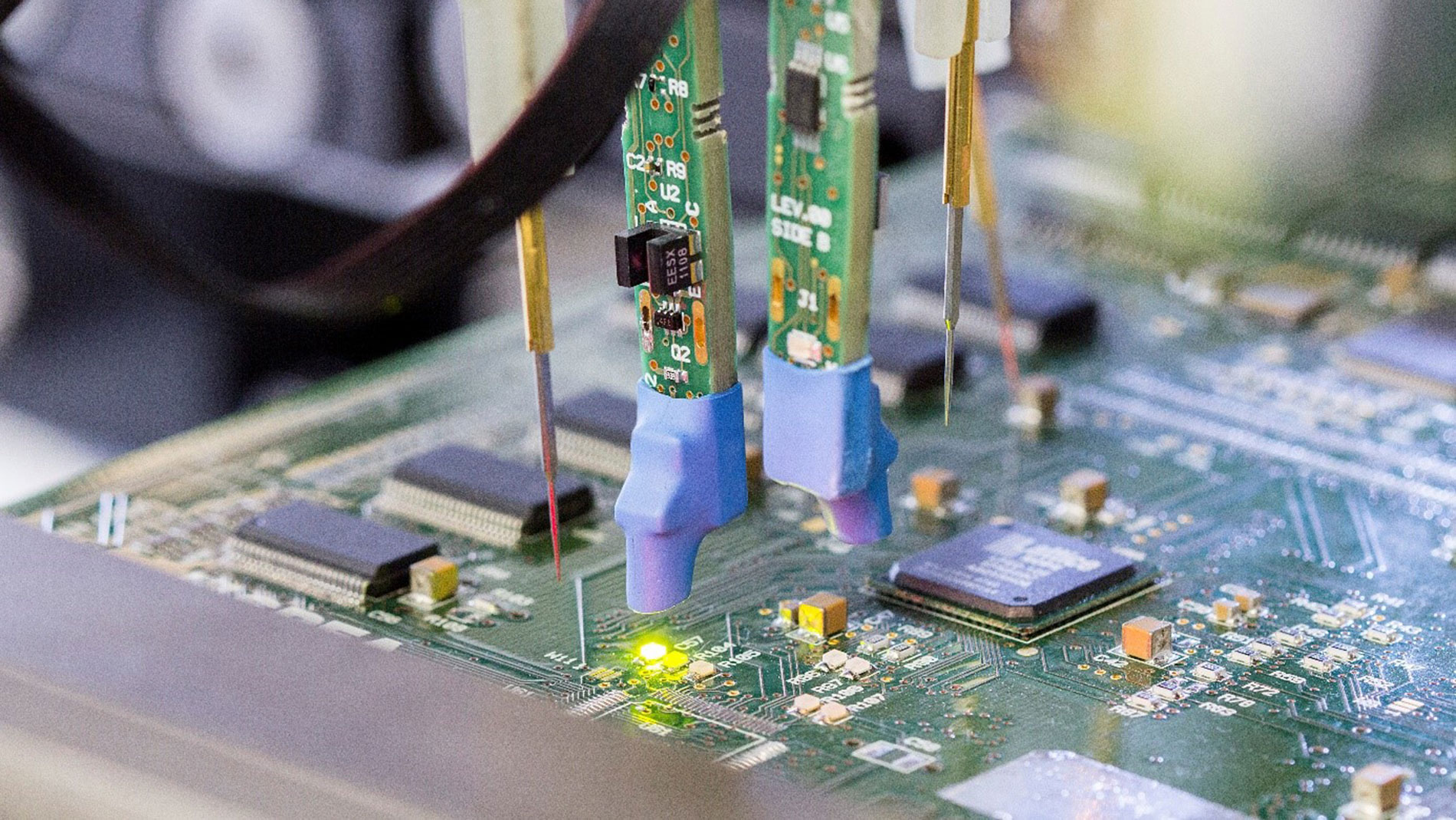
Fig. 1: SPEA testers work with spectrometers for specific and high-precision LED measurement (Figure: SPEA GmbH)
With SPEA systems, assemblies with dimensions of up to 684 mm x 610 mm can be tested, also overlong assemblies up to 150 cm as well as assemblies with high components (components up to 150 mm). A special feature is that the measuring instruments are positioned directly at the probes. This allows the measuring signal to be recorded directly - without losses via cable feed lines. A laser measures the height profile of the assembly. Deflections and distortions are detected and the positioning of the test needles is automatically corrected by the software. Spectrometers guarantee specific and high-precision LED measurements (Fig. 1). In addition to the test probes, additional tools as well as measuring and test instruments can be attached to the axes, e.g. Electro Scan for open-pin detection, NZT for specific impedance analysis, marking units for good/bad marking, contrast fingers to support the assembly, and many more. Finally, when selecting a system, it must be taken into account that there will always be new test requirements that the systems will have to meet in the future.