To test the solderability of parts, components and substrates, you can proceed manually or automatically. If you take a closer look at the pros and cons of both methods, there is a lot to be said for using a solderability test.
The D&L test (Dip and Look) is a manual method in which the test object is completely immersed in molten solder and then visually inspected.
A test piece is dipped into a molten solder bath, usually by an operator. The surfaces to be wetted are first wetted with flux and then completely immersed in the solder. After a defined time, the test specimen is pulled out of the solder again and needs to cool down. Then the soldering point is visually inspected and only the surface of the solder is evaluated. However, only the outer layer of the cooled solder on the solder joint and its characteristics, surface structure and quality can be assessed. In order to obtain useful results, the following questions should be answered or aspects defined:
Which parameters are used to make the tests?
(immersion depths, speeds, temperature, viewing, illumination, table of evaluation and viewing guidelines etc.)
Is the test performed by an operator or by a machine?
Which calibration certificates are used?
What training protocols are used?
How is the human factor excluded when viewing the solder after cooling?
Is the result made by one viewer or confirmed by several viewers?
Are there reference components?
Are there specifications for the settings on the microscope and the illumination?
Is a microscope used? Is the sitting position of the operator defined to ensure a constant view through the microscope?
Are there specifications for the times at the microscope?
Which light source is used (daylight, halogen, LED, wavelength)?
At what times of day are the observations made?
Are the results correlated with a measuring device like an LBT?
Are parallel components installed in a production line and checked after aging and thermocycling?
Are the flux residues removed before the observation? And if so, how?
These aspects show the complexity of a solderability test. If the above points are clarified, the D&L test is cheap and easy to perform. However, since it is not a measurement method in the true sense of the word, this method comes with various limitations: There is no consistently standardized procedure. And the visual assessment of the outer solder surface after the solder joint has cooled down depends strongly on the experience and approach of the person concerned.
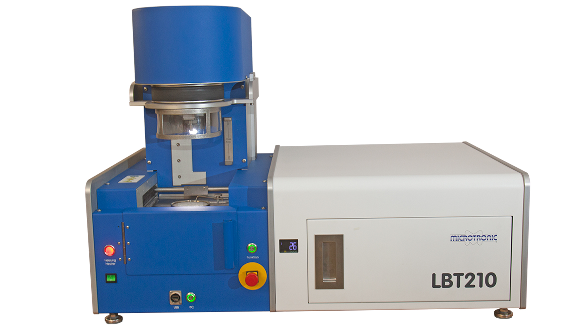
Picture 1: LBT 210 for efficient and safe solderability tests (Picture: Microtronic M. V. GmbH)
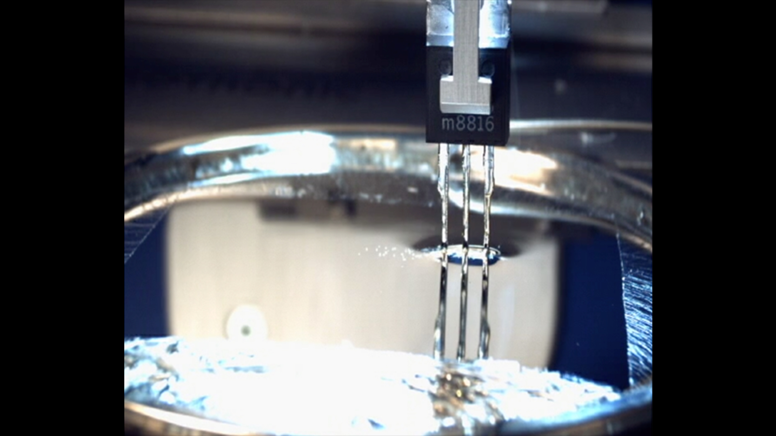
In an LBT (solderability test), the test object is partially immersed in a solder bath (or a ball in the case of small components) using a calibrated machine (Picture 1) – always the same. During the soldering process, the force is absorbed which is created by the interaction of the surface tension of the solder and the wetting force. All process parameters are also set in the LBT program. The component is picked up by a holder (usually a form of clamp), wetted with flux and placed in the LBT. The measuring sequence is started.
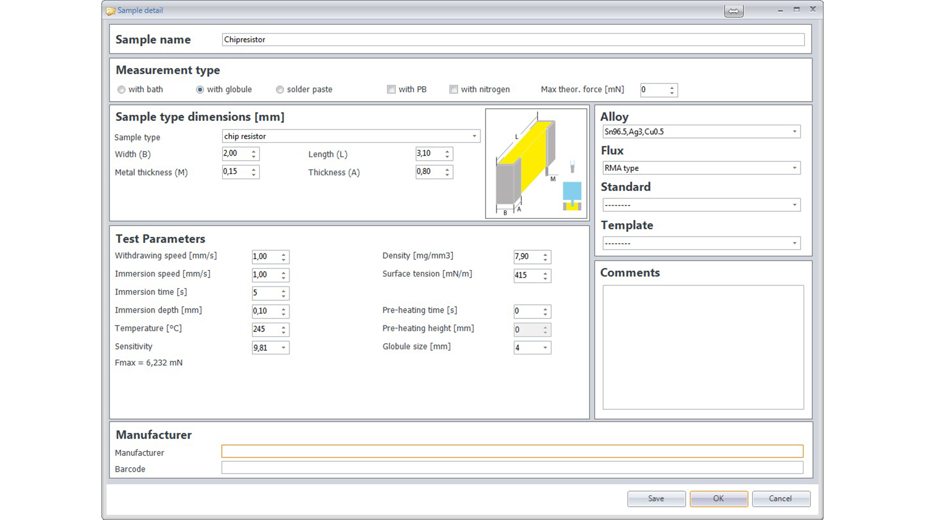
Picture 2: Clearly selecting the relevant parameters (Picture: Microtronic M. V. GmbH)
The LBT removes the oxide from the solder bath. Then the position (length) of the test piece and the level of the solder bath are measured so that the test piece can be immersed exactly as deep as specified in the software (Picture 2). The LBT then moves the test piece into the molten solder at the set speed. The temperature window of the solder must be ± 3 °C. After the test time has expired, the component is moved out of the solder bath again at the set speed. During the entire time between immersion and withdrawal, the force acting on the component is absorbed by a mechanically free measuring sensor.
Picture 2: Clearly selecting the relevant parameters (Picture: Microtronic M. V. GmbH)
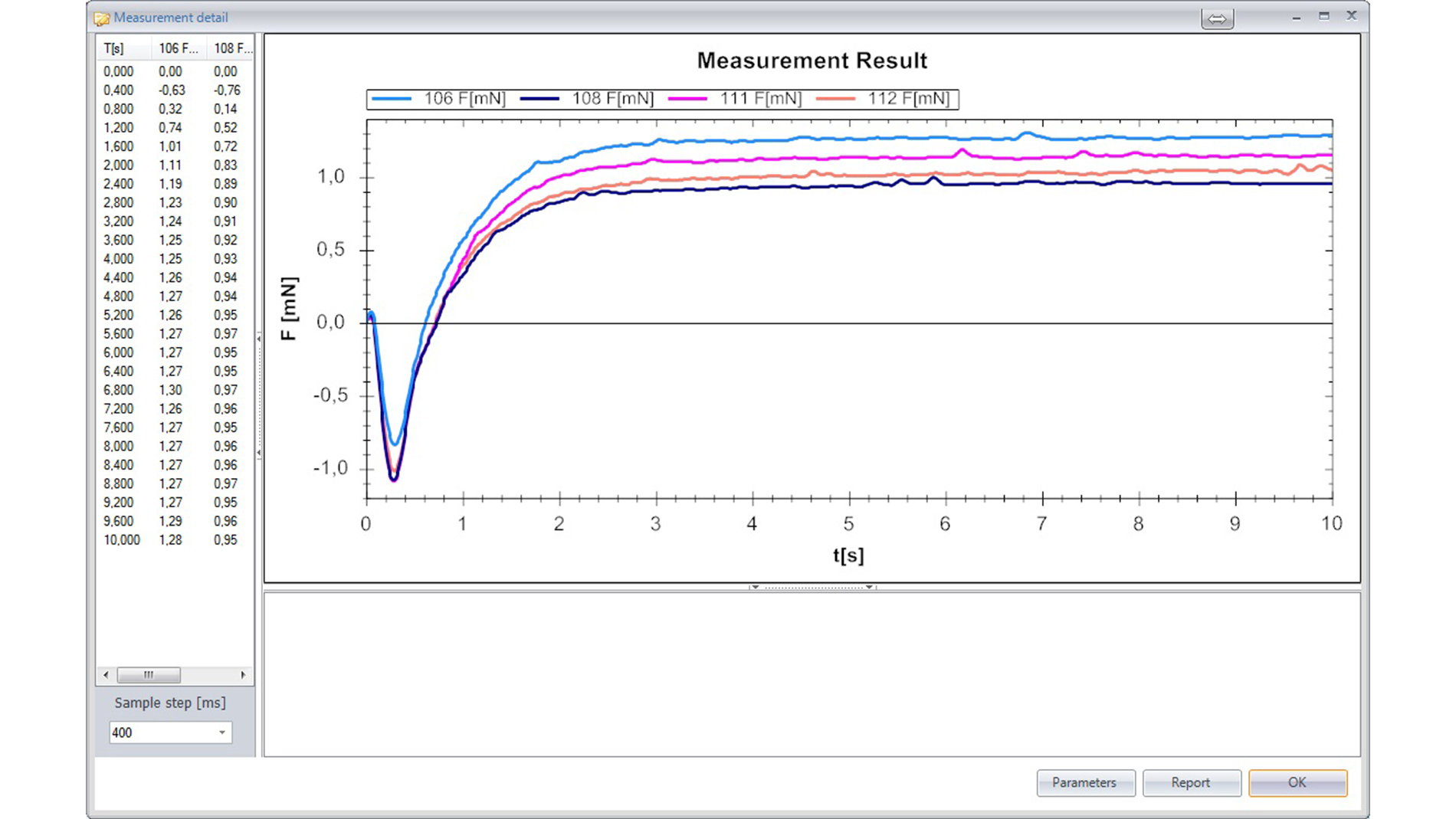
Picture 3: Example results of three measurements at a glance (Figure: Microtronic M. V. GmbH)
The software then displays this as a graphic curve. By means of the entered dimensions of the test piece, the theoretical maximum soldering force that can be achieved with this test piece under optimum conditions can be calculated. Alternatively, this force can also be measured and stored as a reference. To evaluate the soldering, the forces at different times and the speed of the soldering are then considered. This is stored and specified in various standards. The software can carry out the evaluation according to the known international and various company-specific standards and output it by Pass/Fail (Picture 3).
In contrast to the D&L test, the LBT is a real measuring method with a consistent and comprehensible procedure. However, the purchase of an LBT requires investment.
"If one compares the differences between the two methods, it must be clearly stated at this point that it is not expedient to look at the solder joint after the solder has cooled down," says Ernst Eggelaar, Managing Director, Microtronic M. V. GmbH. "This method says something about the quality of the soldering at most indirectly.”
Because the operator cannot even see the solder joint itself. Nor does it consider what happens during the soldering process. Only the finished result is visible - whether, for example, the soldering is fast, slow, gradual, with variable increase etc. cannot be observed. In the end, the D&L only shows whether solder is there or not and whether the solder has gross deviations from the target. However, this is not an assessment of the soldering in and of itself and does not replace a measurement in which real measured values are obtained under constant conditions.
Picture 3: Example results of three measurements at a glance (Figure: Microtronic M. V. GmbH)
"Therefore, in view of the increasing quality requirements in the electronics industry, an LBT is preferable in most cases."